Page 1 of 2 1 2 LastLast
Results 1 to 20 of 30

Thread: I need some help badly guys, don't want to trash it...

  1. #1
    Blind Shooter addicted2dunes's Avatar
    Join Date
    May 2013
    Location
    Orcutt, CA
    Posts
    61
    Thanks
    15
    Thanks Received
    81

    Unhappy I need some help badly guys, don't want to trash it...

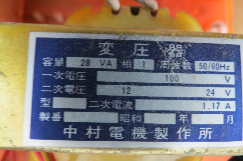
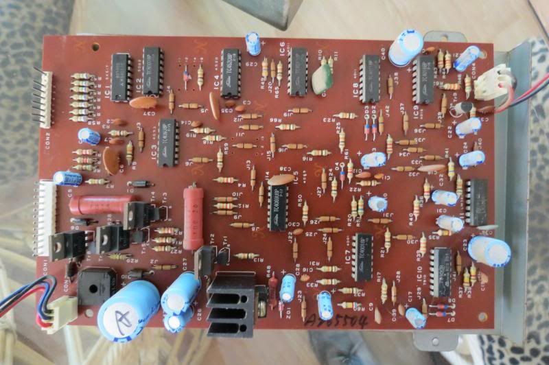
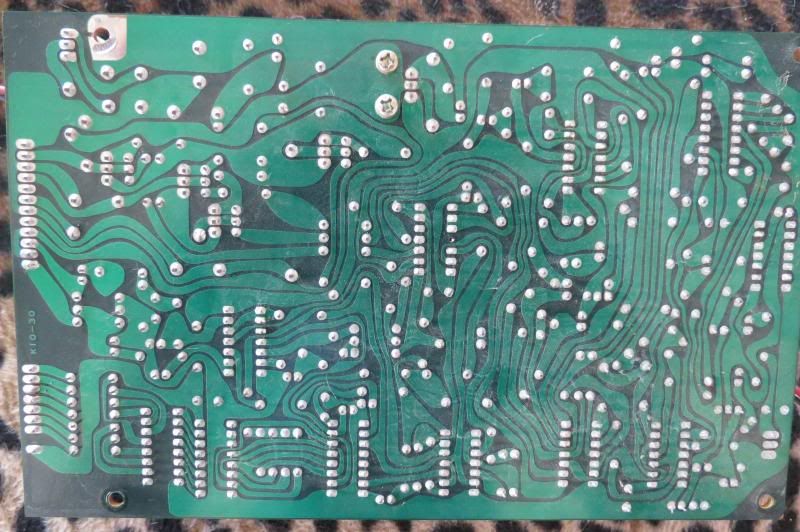
    OK, my wife's machine has been working fine for about the six months we have owned it. All of a sudden in the middle of the night the jackpot music started to play, so I went and unplugged it. Now something fishy is going on, when I plug the machine in it acts like it doesn't have enough power. The jackpot light works, the music is very, very quiet, and the counter in the middle is real dim and sometimes goes out. Also, when you get it in the jackpot it used to flip all the tulips up, now it doesn't. Now I'm no stranger to electrical, I love it so first things first, I checked the transformer out, I am getting good voltage, about 14 on the 12 volt side and 29 on the 24 volt side... Is something wrong with the board? Is it fixable or trash? I don't know much about the machine though... here are some pics to help out (pics are from when it worked correctly):


    Any help is much appreciated! My wife loves this machine and it is really sentimental to her. Thanks guys!

  2. #2
    Goodwill Ambassador luckydog's Avatar
    Join Date
    Nov 2004
    Location
    bradenton, florida
    Posts
    31,487
    Thanks
    13,448
    Thanks Received
    24,112

    Default Re: I need some help badly guys, don't want to trash it...

    I would say get a new transformer, the one you have may have been partly damaged.

    never leave a machine with a transformer plugged in at nite, we all use power strips and shut those off.

    your lucky you didn't have a fire!!!
    幸運わんわん Luckydog or Yukiwanwan in Japanese

  3. The following 4 users say "Thanks" to luckydog


  4. #3
    Eye Shooter heima's Avatar
    Join Date
    Jun 2013
    Location
    SFBayArea
    Posts
    776
    Thanks
    368
    Thanks Received
    664

    Default Re: I need some help badly guys, don't want to trash it...

    Have you checked all electrical connections? Some look a little groady.
    How about fuses?
    Switches?
    Hmm, your voltages are inline with a Japanese transformer being used in the US. Do the ratings printed on the transformer substantiate that?
    Maybe you could consider the affects of too high of voltage for a sustained period.
    I am just taking a guess here, I see electrolytic caps inside the "blackbox" It might be that one or two has gone out. If so, those can be replaced.
    Da' Horse!

    Don't F with Pachinko Machines, Man !

  5. The following user says "Thanks" to heima


  6. #4
    Blind Shooter addicted2dunes's Avatar
    Join Date
    May 2013
    Location
    Orcutt, CA
    Posts
    61
    Thanks
    15
    Thanks Received
    81

    Default Re: I need some help badly guys, don't want to trash it...

    Quote Originally Posted by luckydog View Post
    I would say get a new transformer, the one you have may have been partly damaged.

    never leave a machine with a transformer plugged in at nite, we all use power strips and shut those off.

    your lucky you didn't have a fire!!!
    Where can I find a double output transformer? Even if it seems to be in specs still?

    Quote Originally Posted by heima View Post
    Have you checked all electrical connections? Some look a little groady.
    How about fuses?
    Switches?
    Hmm, your voltages are inline with a Japanese transformer being used in the US. Do the ratings printed on the transformer substantiate that?
    Maybe you could consider the affects of too high of voltage for a sustained period.
    I am just taking a guess here, I see electrolytic caps inside the "blackbox" It might be that one or two has gone out. If so, those can be replaced.
    Connections all good and clean
    Switches I believe are all good
    Fuses are all good

    Ratings on the transformer say 24 and 12 volts, all are within specs now

    electrolytic caps? You lost me? If it is, where can I find those?

  7. #5
    Eye Shooter heima's Avatar
    Join Date
    Jun 2013
    Location
    SFBayArea
    Posts
    776
    Thanks
    368
    Thanks Received
    664

    Default Re: I need some help badly guys, don't want to trash it...

    Yes, the outputs on the ratings is 24 and 12, but what is the input rating?
    The outputs are within specs now? Meaning you are measuring and getting 24 volts, not 29 volts, and 12 volts, not 14 volts?
    If that is the case, why did they change? What was connected/disconnected when you took the readings?

    Crucial to troubleshooting is the process of elimination. The more unknowns, the more possibilities of cause, the more time to troubleshoot. Be certain that things are "good".

    The "blackbox" is the box having the circuit board inside. It looks a little greenish gray in the photos. I can see electrolytic capacitors through the vent holes.
    Electrolytic capacitors of older electronics have a reputation of failing. The dilectric fluid inside leaches out over time lowering the performance of the capacitor, shorting the plates, or corroding the circuit board under the capacitor.

    Most likely that circuit board has diodes and transistors. When subjected to over voltage or over current, these can fail.

    I would believe the circuit board uses DC power to drive its logic circuits. That means AC has to be converted to DC somewhere. That could be on the circuit board, or with another component. The conversion circuit uses capacitors and diodes. If 29 volts was being applied to the conversion circuit, it might have shortened its life. 29 volts is 21% more than 24 volts.

    I am not familiar with this type of pachinko, but this is what I would do if it was my machine.
    Pachinko unplugged from wall.
    1. Digital MultiMeter (DMM) set to Ohms, measure resistance through each connector.
    2. DMM set to Ohms,measure resistance through each switch.
    3. DMM set to Ohms, measure resistance through each fuse.
    Pachinko plugged into wall, powered on.
    4. DMM set to AC volts, measure voltage on every terminal of every transformer.
    5. DMM set to AC volts, measure voltage through wires and connectors from transformers.
    Follow where AC voltage wires go for AC to DC conversion.
    6. DMM set to DC volts, measure voltage at AC to DC conversion device.
    7. DMM set to DC volts, measure voltage through wires and connectors from conversion device.
    If everything is fine so far, unplug pachinko from wall. Disconnect wires from box. Remove box from pachinko. Open box and remove circuit board.
    8. Inspect circuit board for hot spots, burn marks, discolorations, stains, corrosion, anything that looks odd.
    9. Inspect the electrolytic capacitors (typically light-blue, light-grey, or black, cylinders) for an "inflated", "blown up", or "expanded" appearance. Is there a stain under the capacitor? Is the black plug showing?
    10. DMM set to diode check, check the diodes (black or glass cylinders lying on side), probes one way should beep and show 0.5 to 0.7, probes the other way should not beep and show nothing or 0.
    11. DMM set to diode check, check the transistors (black or silver, with three wires), transistors can be checked like two diodes together. There are six combinations of how the probes can be attached. You should get the beep and about 0.7 for only two of the ways.

    If you have diagnosed that the problem is in the box, but you don't feel comfortable pursuing the troubleshooting any further, there are many people here who do restorations and they might be willing to take a look at your circuit board for a nominal fee.
    Da' Horse!

    Don't F with Pachinko Machines, Man !

  8. The following 2 users say "Thanks" to heima


  9. #6
    Blind Shooter addicted2dunes's Avatar
    Join Date
    May 2013
    Location
    Orcutt, CA
    Posts
    61
    Thanks
    15
    Thanks Received
    81

    Default Re: I need some help badly guys, don't want to trash it...

    Quote Originally Posted by heima View Post
    Yes, the outputs on the ratings is 24 and 12, but what is the input rating? I do not know, I can't read the writing, My input is 121.1v AC
    The outputs are within specs now? Meaning you are measuring and getting 24 volts, not 29 volts, and 12 volts, not 14 volts? No, exact is 30.02v AC and 15v AC
    If that is the case, why did they change? What was connected/disconnected when you took the readings? No change, I just figured that they were in range at 29 and 14

    Crucial to troubleshooting is the process of elimination. The more unknowns, the more possibilities of cause, the more time to troubleshoot. Be certain that things are "good".

    The "blackbox" is the box having the circuit board inside. It looks a little greenish gray in the photos. I can see electrolytic capacitors through the vent holes.
    Electrolytic capacitors of older electronics have a reputation of failing. The dilectric fluid inside leaches out over time lowering the performance of the capacitor, shorting the plates, or corroding the circuit board under the capacitor.

    Most likely that circuit board has diodes and transistors. When subjected to over voltage or over current, these can fail.

    I would believe the circuit board uses DC power to drive its logic circuits. That means AC has to be converted to DC somewhere. That could be on the circuit board, or with another component. The conversion circuit uses capacitors and diodes. If 29 volts was being applied to the conversion circuit, it might have shortened its life. 29 volts is 21% more than 24 volts. I don't see anything that would change the voltage from AC to DC?

    I am not familiar with this type of pachinko, but this is what I would do if it was my machine.
    Pachinko unplugged from wall.
    1. Digital MultiMeter (DMM) set to Ohms, measure resistance through each connector.
    2. DMM set to Ohms,measure resistance through each switch.
    3. DMM set to Ohms, measure resistance through each fuse.
    Pachinko plugged into wall, powered on.
    4. DMM set to AC volts, measure voltage on every terminal of every transformer.
    5. DMM set to AC volts, measure voltage through wires and connectors from transformers.
    Follow where AC voltage wires go for AC to DC conversion.
    6. DMM set to DC volts, measure voltage at AC to DC conversion device.
    7. DMM set to DC volts, measure voltage through wires and connectors from conversion device.
    If everything is fine so far, unplug pachinko from wall. Disconnect wires from box. Remove box from pachinko. Open box and remove circuit board.
    8. Inspect circuit board for hot spots, burn marks, discolorations, stains, corrosion, anything that looks odd. None found
    9. Inspect the electrolytic capacitors (typically light-blue, light-grey, or black, cylinders) for an "inflated", "blown up", or "expanded" appearance. Is there a stain under the capacitor? Is the black plug showing? None found
    10. DMM set to diode check, check the diodes (black or glass cylinders lying on side), probes one way should beep and show 0.5 to 0.7, probes the other way should not beep and show nothing or 0. Diode check? What setting?
    11. DMM set to diode check, check the transistors (black or silver, with three wires), transistors can be checked like two diodes together. There are six combinations of how the probes can be attached. You should get the beep and about 0.7 for only two of the ways.

    If you have diagnosed that the problem is in the box, but you don't feel comfortable pursuing the troubleshooting any further, there are many people here who do restorations and they might be willing to take a look at your circuit board for a nominal fee.
    As I do more investigating I will update the list above. I do want to thank you very much for the write up, that is awesome! I just don't see any diodes (black or glass cylinders lying on side).
    Is the Transistor the silver top with hole, black mid section, and the three legs going in?
    Also, I will post more pics in a second...

  10. #7
    Blind Shooter addicted2dunes's Avatar
    Join Date
    May 2013
    Location
    Orcutt, CA
    Posts
    61
    Thanks
    15
    Thanks Received
    81

    Default Re: I need some help badly guys, don't want to trash it...

    My meter:


    Transformer:


    Circuit Board:


  11. The following 5 users say "Thanks" to addicted2dunes


  12. #8
    Eye Shooter heima's Avatar
    Join Date
    Jun 2013
    Location
    SFBayArea
    Posts
    776
    Thanks
    368
    Thanks Received
    664

    Default Re: I need some help badly guys, don't want to trash it...

    Thanks for the pictures. They speak volumes.
    In the meter picture, you have it set for volts. The next setting clockwise is for ohms. The setting after that is the diode check.
    You have a transformer for use in Japan. Not the US. The 100 V gives that fact away. You need a transformer for the US. Radio shack sells a transformer you can use 25.2V CT 2.0A Heavy-Duty Chassis-Mount Transformer with Lead : Transformers | RadioShack.com
    In the picture of the circuit board, component side. I see plenty of capacitors and diodes and transistors. Yes, pretty much anything with three wires is a transistor.
    If you were to take the circuit board and divide it into 4 pieces, the lower left piece is the AC to DC conversion section. You have a few diodes there, some transistors, and some capacitors.
    A couple of the diodes there look like they got toasty. Not burned, but hot. Black diodes have silver writing on them. The silver looks brown. The black diode next to the electrical connection with a red, blue and black wire looks suspect.
    In the lower right corner are two glass diodes. So now you can realize how many diodes are on this circuit board.
    There is a transistor with a big black heat sink on it. Is the lettering on that transistor LM7805?
    If so, this in fact is a 5 volt voltage regulator. This provides filtered regulated power to the logic chips. Do not perform the diode check on it as it will not check the regulator.
    The board has naming of the component as well.
    Cnumber capacitor number
    CONnumber connector number
    Dnumber diode number
    Jnumber jumper number (this is an interesting board because the jumper looks like a resistor. A jumper is just a conductor,a wire, nothing special about it)
    ICnumber integrated circuit number (it looks like most of these do the logic)
    Rnumber resistor number
    Trnumber transistor number
    ZDnumber Zener diode number (zener diodes are like mini voltage regulators, you can check them like regular diodes, but the best way to check them is more involved.)

    The black square with a small hole in the center is the rectifier. It turns AC voltage into a "messy" DC voltage. The other components near the rectifier clean up the DC voltage and regulate it.
    In normal operation the power resistors, the big red cylinders on their side, will feel warm, possibly hot.

    So, now that you know what capacitors, diodes and transistors look like, time to get to work.
    Da' Horse!

    Don't F with Pachinko Machines, Man !

  13. The following 2 users say "Thanks" to heima


  14. #9
    Blind Shooter addicted2dunes's Avatar
    Join Date
    May 2013
    Location
    Orcutt, CA
    Posts
    61
    Thanks
    15
    Thanks Received
    81

    Default Re: I need some help badly guys, don't want to trash it...

    Quote Originally Posted by heima View Post
    You have a transformer for use in Japan. Not the US. The 100 V gives that fact away. You need a transformer for the US. Radio shack sells a transformer you can use 25.2V CT 2.0A Heavy-Duty Chassis-Mount Transformer with Lead : Transformers | RadioShack.com Ordered, Thanks!

    A couple of the diodes there look like they got toasty. Not burned, but hot. Black diodes have silver writing on them. The silver looks brown. They are all brown but look originally brown?

    There is a transistor with a big black heat sink on it. Is the lettering on that transistor LM7805? No, there are three numerical lines, top is "T", middle is "D880, Bottom is "Y *2E"
    Quote Originally Posted by heima View Post
    Yes, the outputs on the ratings is 24 and 12, but what is the input rating? 100v

    The outputs are within specs now? Meaning you are measuring and getting 24 volts, not 29 volts, and 12 volts, not 14 volts? No, exact is 30.02v AC and 15v AC

    Pachinko unplugged from wall.
    1. Digital MultiMeter (DMM) set to Ohms, measure resistance through each connector.
    2. DMM set to Ohms,measure resistance through each switch.
    3. DMM set to Ohms, measure resistance through each fuse.

    Pachinko plugged into wall, powered on.
    4. DMM set to AC volts, measure voltage on every terminal of every transformer.
    5. DMM set to AC volts, measure voltage through wires and connectors from transformers.
    Follow where AC voltage wires go for AC to DC conversion.
    6. DMM set to DC volts, measure voltage at AC to DC conversion device.
    7. DMM set to DC volts, measure voltage through wires and connectors from conversion device.

    If everything is fine so far, unplug pachinko from wall. Disconnect wires from box. Remove box from pachinko. Open box and remove circuit board.
    8. Inspect circuit board for hot spots, burn marks, discolorations, stains, corrosion, anything that looks odd. None Found
    9. Inspect the electrolytic capacitors (typically light-blue, light-grey, or black, cylinders) for an "inflated", "blown up", or "expanded" appearance. Is there a stain under the capacitor? Is the black plug showing? All Look Good
    10. DMM set to diode check, check the diodes (black or glass cylinders lying on side), probes one way should beep and show 0.5 to 0.7, probes the other way should not beep and show nothing or 0.
    D1 - .57/0
    D2 - .60/0 Glass
    D3 - .62/0 Glass
    D4 - .61/0 Glass
    D5 - .57/0
    D6 - .58/0
    D7 - .62/1.09 Glass Bad?
    D8 - .60/.11 Glass Bad?
    D9 - .80/0 Bad?
    D10 - .57/0
    12 - .62/0 Glass

    11. DMM set to diode check, check the transistors (black or silver, with three wires), transistors can be checked like two diodes together. There are six combinations of how the probes can be attached. You should get the beep and about 0.7 for only two of the ways. Two or three ways, I get all in three

    TR1 - .71/.71/.61/0/0/0
    TR2 - .94/.61/.61/0/0/0 Bad?
    TR3 - .72/.71/.60/0/0/0
    TR4 - .60/.60/1.5/0/0/0 Bad?
    TR5 - .60/.71/.71/0/0/0
    TR6 - .60/.60/1.1/0/0/0 Bad?
    TR7 - .61/.72/.71/0/0/0
    TR8 - .61/.61/1.1/0/0/0 Bad?
    TR9 - .71/.71/0/0/0/0 Bad?
    TR10 - .53/.37/.53/.37/0/0 Heatsinked TR Bad?
    I deleted my post above to avoid a lot of confusion, combined into one... I really do appreciate all the help thus far!

    Edit: I guess I can't delete my post above... huh

  15. #10
    Eye Shooter heima's Avatar
    Join Date
    Jun 2013
    Location
    SFBayArea
    Posts
    776
    Thanks
    368
    Thanks Received
    664

    Default Re: I need some help badly guys, don't want to trash it...

    Thank you very much for taking these measurements. I know that took a lot of dilligence to measure and write down the values.
    Hmm, its late and my brain is having trouble thinking this through. Yes, D7 and D8 seem odd. Especially because they are wired in series. I am guessing it is to double the voltage drop. Still, their reverse voltages seems odd. D9 does seem a little high, but I am not certain what in the circuit might affect that value. I think the reason you got three values for the transistors Tr1 through Tr8 is because I just realized that they are paired up. Tr1 is paired with Tr2, Tr3 with Tr4, and so on. Paired transistors are used for amplifying a signal or switching a high current signal. I am guessing here that they might be used for the ball shooter. I could be wrong. Are there 4/5 wires going to the ball shooter motor? Alternatively, these pairs might be driving solenoids. Are the tulips electrically controlled?
    Tr10 The D880y is a NPN power transistor I am trying to figure out its purpose.
    Can you tell me what is printed on IC10 and IC11?
    Also, how good are you with a soldering iron?
    Da' Horse!

    Don't F with Pachinko Machines, Man !

  16. The following 3 users say "Thanks" to heima


  17. #11
    Blind Shooter addicted2dunes's Avatar
    Join Date
    May 2013
    Location
    Orcutt, CA
    Posts
    61
    Thanks
    15
    Thanks Received
    81

    Default Re: I need some help badly guys, don't want to trash it...

    Quote Originally Posted by heima View Post
    I am guessing here that they might be used for the ball shooter. I could be wrong. Are there 4/5 wires going to the ball shooter motor? 3 wires, and no, the shooter is powered directly off the incoming voltage
    Alternatively, these pairs might be driving solenoids. Are the tulips electrically controlled? The tulips are electrically controlled
    Tr10 The D880y is a NPN power transistor I am trying to figure out its purpose.
    Can you tell me what is printed on IC10 and IC11? IC10 is 7910CR, and IC11 is LM380N
    Also, how good are you with a soldering iron? Very good
    Again, awesome help!

  18. The following user says "Thanks" to addicted2dunes


  19. #12
    Eye Shooter heima's Avatar
    Join Date
    Jun 2013
    Location
    SFBayArea
    Posts
    776
    Thanks
    368
    Thanks Received
    664

    Default Re: I need some help badly guys, don't want to trash it...

    Hmmm, as I suspected the IC10 is the music maker. 7910CR EPSON Electronics, 7910CR Datasheet and IC11 is the amplifier for it. http://www.ti.com/lit/ds/symlink/lm380.pdf

    If you have a good soldering iron, something in the 20 watt range, desolder one lead of D7, D8, and D9 and then measure them again. By desoldering one lead and lifting it out of the circuit board, you are taking the diode out of the circuit and hopefully we can get a better measurement from them. My fingers are crossed that something is wrong with D9 primarily, and then D7 and D8.
    If they check out ok, there are other areas to investigate, like that big capacitor with the "A" on it and the two next to it.
    Good Luck.
    WARNING - Do not use a soldering iron that is any hotter than 25 watts, as there is a great chance you will damage the circuit board.

    As an aside, it looks like IC1 and IC2 are used to drive the LED display through CON2. And I am guessing that the speaker connects at CON4?
    Oh, and just for good measure, what are the resistances, in ohms, of the two big red power resistors, and the little red power resistors, and what is printed on them?
    Thanks
    Da' Horse!

    Don't F with Pachinko Machines, Man !

  20. The following 2 users say "Thanks" to heima


  21. #13
    Blind Shooter addicted2dunes's Avatar
    Join Date
    May 2013
    Location
    Orcutt, CA
    Posts
    61
    Thanks
    15
    Thanks Received
    81

    Default Re: I need some help badly guys, don't want to trash it...

    Quote Originally Posted by heima View Post
    Hmmm, as I suspected the IC10 is the music maker. 7910CR EPSON Electronics, 7910CR Datasheet and IC11 is the amplifier for it. http://www.ti.com/lit/ds/symlink/lm380.pdf

    If you have a good soldering iron, something in the 20 watt range, desolder one lead of D7, D8, and D9 and then measure them again. By desoldering one lead and lifting it out of the circuit board, you are taking the diode out of the circuit and hopefully we can get a better measurement from them. My fingers are crossed that something is wrong with D9 primarily, and then D7 and D8.
    If they check out ok, there are other areas to investigate, like that big capacitor with the "A" on it and the two next to it.
    Good Luck.
    WARNING - Do not use a soldering iron that is any hotter than 25 watts, as there is a great chance you will damage the circuit board.

    As an aside, it looks like IC1 and IC2 are used to drive the LED display through CON2. And I am guessing that the speaker connects at CON4? Speaker is in CON4
    Oh, and just for good measure, what are the resistances, in ohms, of the two big red power resistors, and the little red power resistors, and what is printed on them? Bigs measure: 51.5 and 50.4 ohms Small measures: 272.4 ohms Bigs say: RS3B 51(OHM)J TDO 2A Small says: RS7(or 1)A 270(OHM)J KAMAYA
    Thanks
    As a side note, if it matters... the music is playing normally but all the time, jackpot or not. Also, the Jackpot lighting seems to be working perfect.

  22. The following user says "Thanks" to addicted2dunes


  23. #14
    Blind Shooter addicted2dunes's Avatar
    Join Date
    May 2013
    Location
    Orcutt, CA
    Posts
    61
    Thanks
    15
    Thanks Received
    81

    Default Re: I need some help badly guys, don't want to trash it...

    Unsoldered
    D7 - .620/0
    D8 - .600/0
    D9 - .563/0

  24. The following 2 users say "Thanks" to addicted2dunes


  25. #15
    Eye Shooter heima's Avatar
    Join Date
    Jun 2013
    Location
    SFBayArea
    Posts
    776
    Thanks
    368
    Thanks Received
    664

    Default Re: I need some help badly guys, don't want to trash it...

    Quote Originally Posted by addicted2dunes View Post
    Unsoldered
    D7 - .620/0
    D8 - .600/0
    D9 - .563/0
    Dammit! I was hoping that D9 was it. Ok, thank you very much for checking them. Please solder them back.
    Thank you very much for your patience, diligence, and determination.

    I did not think it would matter, but while we are at it, lets check the bridge rectifier. This is the black square with the small hole in the middle. Inside of the square are four diodes. They are joined both in parallel and series and form a square inside the plastic. You might see markings for + , -, and either "AC" or ~. The voltage from the transformer comes into the bridge rectifier at the AC or ~ and leaves at the + and -. To test the rectifier, you will need to work on the solder side of the circuit board. There are 4 solder points. There is a diode between adjacent solder points, four diodes around the square. Now you get to do a diode check all around the rectifier. 8 checks in all. You do not need to check the diagonals.

    I have my fingers crossed that something comes up. Good Luck!

    Also, what are the markings on the big capacitors? The three in the AC to DC conversion area, and the other two big ones?
    Da' Horse!

    Don't F with Pachinko Machines, Man !

  26. The following 3 users say "Thanks" to heima


  27. #16
    Blind Shooter addicted2dunes's Avatar
    Join Date
    May 2013
    Location
    Orcutt, CA
    Posts
    61
    Thanks
    15
    Thanks Received
    81

    Default Re: I need some help badly guys, don't want to trash it...

    Quote Originally Posted by heima View Post
    I did not think it would matter, but while we are at it, lets check the bridge rectifier. This is the black square with the small hole in the middle. Inside of the square are four diodes. They are joined both in parallel and series and form a square inside the plastic. You might see markings for + , -, and either "AC" or ~. The voltage from the transformer comes into the bridge rectifier at the AC or ~ and leaves at the + and -. To test the rectifier, you will need to work on the solder side of the circuit board. There are 4 solder points. There is a diode between adjacent solder points, four diodes around the square. Now you get to do a diode check all around the rectifier. 8 checks in all. You do not need to check the diagonals. .607/0/0/.573/0/0/0/0

    I have my fingers crossed that something comes up. Good Luck!

    Also, what are the markings on the big capacitors? The three in the AC to DC conversion area, and the other two big ones?
    A marked is: 50v470uf
    50v47uf
    25v470uf
    25v220uf
    6.3v470uf
    If only it was that easy...

  28. #17
    Eye Shooter Chumsize's Avatar
    Join Date
    Aug 2012
    Location
    Gilroy, CA
    Posts
    887
    Thanks
    516
    Thanks Received
    1,785

    Default Re: I need some help badly guys, don't want to trash it...

    Looking back at this thread... it seems like you left this plugged in for long periods of time? So we're looking for a part that melted down over a long period...

    There's dust on one side of everything in the pic... Think you could de-dust it and send it again? Under the dust there may be some telltale burns somewhere.

    Otherwise, the only three that look at all "old and weepy" to me are the same diodes Heima is asking about.


    How far away from SF/San Jose is Orcutt anyway? Always an option... Maybe trade you another slightly less old machine...
    Woof!

  29. #18
    Eye Shooter heima's Avatar
    Join Date
    Jun 2013
    Location
    SFBayArea
    Posts
    776
    Thanks
    368
    Thanks Received
    664

    Default Re: I need some help badly guys, don't want to trash it...

    Quote Originally Posted by addicted2dunes View Post
    If only it was that easy...
    Thank you addicted2dunes. Maybe we found our culprit. Checking the bridge rectifier, you should have gotten 4 good diode values, but you only got 2, so this means two diodes are bad. I am sorry but I have to ask you to desolder the bridge rectifier from the circuit board and check it again. Here is a picture of what is inside a bridge rectifier.
    bridge.jpg
    by this design, if any two adjacent diodes were bad, then no power would get out. If any two opposite diodes were bad, then power could get out, but in that case, the power is pulsed.

    Maybe we found the troublemaker. Damn I hope that is it.
    Radio Shack sells a lot of different bridge rectifiers online, but in the store, this one:
    25A, 50V Full-Wave Bridge Rectifiers : Rectifiers | RadioShack.com
    or this one:
    RadioShack 8A/400V Full-Wave Bridge Rectifiers : Rectifiers | RadioShack.com
    or this one if you bend the legs to accommodate the circuit board:
    4A, 400V Full-Wave Bridge Rectifiers : Rectifiers | RadioShack.com
    should work for you.
    The problem is the physical size of the bridge rectifier. But I am jumping ahead, we still need to get the old bridge rectifier desoldered off and verified it is bad. If it is bad, there might be some printing on it that will tell us what voltage and current values it is designed for.
    Fingers and toes crossed here...
    Da' Horse!

    Don't F with Pachinko Machines, Man !

  30. The following 2 users say "Thanks" to heima


  31. #19
    I was thrown out of Top Gear Drunkenclam's Avatar
    Join Date
    May 2010
    Location
    Guildford, Surrey
    Posts
    28,583
    Thanks
    13,484
    Thanks Received
    18,894

    Default Re: I need some help badly guys, don't want to trash it...

    There is something printed on the side, But can't make it out from the picture, Looks like a 2 and a 0 with a symbol in front, But hopefully you will be able to have a closer look for any markings later.
    Ian #UKPachinko

  32. #20
    Blind Shooter addicted2dunes's Avatar
    Join Date
    May 2013
    Location
    Orcutt, CA
    Posts
    61
    Thanks
    15
    Thanks Received
    81

    Default Re: I need some help badly guys, don't want to trash it...

    Quote Originally Posted by Chumsize View Post
    Looking back at this thread... it seems like you left this plugged in for long periods of time? So we're looking for a part that melted down over a long period...

    There's dust on one side of everything in the pic... Think you could de-dust it and send it again? Under the dust there may be some telltale burns somewhere.

    Otherwise, the only three that look at all "old and weepy" to me are the same diodes Heima is asking about.


    How far away from SF/San Jose is Orcutt anyway? Always an option... Maybe trade you another slightly less old machine...
    As stated in the first post, I don't want to get rid of the machine... This machine is very sentimental to my wife.

Page 1 of 2 1 2 LastLast

Similar Threads

  1. Fixing badly pitted chrome
    By Ash in forum Vintage Pachinko
    Replies: 12
    Last Post: 12-18-2012, 03:54 PM
  2. Trash?
    By ReverendC in forum Vintage Pachinko
    Replies: 26
    Last Post: 05-27-2011, 01:54 PM
  3. Trailer Trash
    By BigBearSteve in forum These are the days of our lives...
    Replies: 10
    Last Post: 01-05-2011, 08:03 PM
  4. trash or treasure??
    By luckydog in forum Members Ebay Auctions
    Replies: 30
    Last Post: 11-02-2009, 04:02 AM

Posting Permissions

  • You may not post new threads
  • You may not post replies
  • You may not post attachments
  • You may not edit your posts
  •